
Where Each Building Belongs: A Master Planning Walkthrough from an Onshore Oil & Gas Plant in Mexico

Actualizado: 31 may
By Fernando Pérez Kaparunakis — ARIA Magazine, Insights

On a plot plan of an Oil & Gas processing plant, the eye goes first to the equipment: slug catchers, compression skids, atmospheric tanks, the flare stack. The buildings — the control room, the laboratory, the dining hall, the warehouse — usually appear later, almost as an afterthought. They shouldn't.
This article is a walkthrough of what I learned working on an onshore Oil & Gas processing project in Mexico, where the early definition of building locations stopped being an architectural exercise and became something else: a process safety, operations and business-continuity decision in disguise.
In facilities of this kind, many of the most expensive decisions are made before there is a foundation, a steel structure or a process line in place. One of the most underestimated is where each building sits within the site. And once you understand what the master plan is actually deciding, you stop seeing a site layout. You start seeing a risk decision.
The master plan as the first layer of safety
In process infrastructure, buildings can be exposed to scenarios such as blast overpressure, fire thermal radiation, releases of flammable or toxic gases, and obstruction of operational or evacuation routes. That is precisely why specific frameworks exist to structure the problem before design progresses.

The practice known as facility siting rests on a fairly consolidated international body of standards: API RP 752 for permanent buildings, API RP 753 for portable buildings, API RP 756 for temporary structures, the CCPS Guidelines for Facility Siting and Layout, and the TNO Yellow Book for physical-effects modeling. On top of that, projects executed by owners and EPC contractors in the sector typically rely on Process Industry Practices — PIP — an industry-harmonized initiative developed as a consortium within The University of Texas at Austin, used to align design, procurement, construction and maintenance criteria. When local regulation enters the picture — in Mexico, for example, the SEMARNAT-07-008 guideline for risk studies on highly hazardous activities — the framework becomes a multi-layered conversation that the master plan has to hold together.
The underlying idea is simple, though uncomfortable: before reinforcing a building, it is worth asking whether it should be there at all. Structural protection — blast-resistant buildings, special reinforcement, hardened envelopes — tends to appear once cheaper decisions are no longer available. Moving a building on paper costs a fraction of hardening it on site, or living with it for the entire operational life.
The numbers that frame the conversation
One reason master plans are discussed badly is that they are discussed without metrics. The useful conversation begins once the thresholds are on the table.
For fire scenarios, the public SEMARNAT criterion defines a high-risk / exclusion zone at 5 kW/m² of thermal radiation, and a buffer zone at 1.4 kW/m². For vapor cloud explosion overpressure, the endpoints are 70 mbar for the exclusion zone and 35 mbar for the buffer. The distinction is not cosmetic: the exclusion zone must stay within the property line; the buffer zone may extend outside the fence, but it shapes neighboring land use, emergency response plans and coordination with local authorities.
Those four numbers — 5 / 1.4 kW/m², 70 / 35 mbar — don't solve the master plan. They organize the conversation. A layout that cannot be read against those thresholds is not a master plan; it is a drawing.
Two approaches that coexist: tables and modeling
The industry works with two complementary approaches when evaluating the location of occupied buildings.
The first is the Spacing Table approach — tables published by CCPS and referenced by API RP 752 — which allows minimum distances between process equipment, occupied buildings and property lines to be defined without detailed modeling. Typical values fall in the 60-to-150-meter range between slug catchers or atmospheric storage tanks and occupied buildings such as control rooms, laboratories, offices and support areas. It is a conservative, fast, early-stage and reasonably defensible approach.

The second is consequence-based modeling: simulation of pool fires and jet fires in tools such as PHAST, and VCE analysis with the TNO Multi-Energy Method or Baker-Strehlow. Here the discussion turns granular. Potential Explosion Areas (PEAs) are identified — typically slug catchers, gas compression skids, congested pipe racks — material reactivity, level of congestion and degree of confinement (2D, 2.5D or 3D) are assigned, and overpressure contours are overlaid on the plot plan.
Neither approach replaces the other. The table disciplines the overall geometry of the site at an early stage; modeling refines the decision where the table leaves room for doubt, or where a critical building — Control Building, Substation/MCC, Emergency Refuge — sits near the edge.
Location as a variable of exposure
Buildings do not share the same level of criticality or occupancy. A control room, a dining hall with permanent occupancy, a maintenance shop, a warehouse, a laboratory, a substation or an emergency refuge follow different logics. Each has its own profile across four variables that are rarely discussed together: occupant permanence inside the building, function during normal operation, function during an emergency, and impact on business continuity if the building is lost.
A dining hall and a control room may look similar on a plot plan, but technically they are different objects. Mixing them within the same zone of the site tends to look like a bad decision in hindsight, even if it is not always visible before commissioning.
Reading the problem this way allows the site to be grouped into technically meaningful zones — process area, operational support, low exposure, critical protected areas — rather than distributing buildings in the order in which they appear in the scope.
In critical infrastructure, a master plan does not organize buildings. It organizes exposure, operation and risk.
A real experience: when the master plan drives engineering
On the onshore Oil & Gas project I worked on in Mexico, the early definition of occupied buildings, headcount profiles and technical requirements made something evident that is often assumed the other way around: technical architecture is not a consequence of the process layout. It is part of the system.

A Control Building, for example, is not a specialized office. It is the point where process supervision, communications, electrical systems, HVAC, redundancy and operational decision-making during an emergency converge. Its location shapes evacuation routes, distances to critical equipment, vehicular access, pressurization and orientation relative to potential release sources. In projects governed by local codes — in this case, seismic criteria from MDOC-CFE 2015 and regional winds with a 200-year return period — the structural classification of the building rests on that location decision.
Its HVAC is not designed for comfort either. In facilities of this type, it typically requires positive pressure, redundancy where operation justifies it, filtered outside air drawn from a non-hazardous area and tight control of indoor conditions throughout the useful life of the building — on the order of 25 years for architectural buildings in these plants. If the air intake is poorly oriented relative to a potential gas source, no façade reinforcement compensates for that decision.
There is another counterintuitive detail that surfaces in these studies: a perimeter wall designed to contain a potential explosion can reduce overpressure outside the fence, but increase it inside the facility through reflection of the blast wave, by a factor of up to roughly two. Solutions that look protective from an external perspective, if poorly coordinated, end up amplifying internal risk. The master plan is where these decisions are debated before they get built.
Inherent safety before blast resistance
The principle that organizes much of the modern facility siting literature is easy to state and hard to apply: when a building is overexposed, the first response is not to harden it; it is to move it. Relocating an Emergency Refuge or a Control Building by a few tens of meters can reduce incident overpressure by meaningful orders of magnitude, eliminating the need for blast-resistant design. Hardening the same building in its original location implies special structure, special envelopes, blast-rated glazing, blast-rated HVAC dampers and higher lifecycle cost.
This does not mean blast resistance has no place. It does, particularly in critical buildings that must remain operable after an event — electrical substations, MCCs, certain control rooms — to enable a safe shutdown. But it should appear as a decision justified by risk, not as an automatic response to a poorly resolved layout.
When mitigation does end up requiring hardening, the materiality follows specific technical criteria: dynamic analysis to define wall and slab thicknesses, connections designed to resist rebound, blast-rated glazing, certified blast-rated doors and HVAC dampers, anchors sized for impulse loading. This body of work rests on references such as ASCE Design of Blast-Resistant Buildings in Petrochemical Facilities and PIP STC01018. It is a discipline of its own and exceeds the scope of the master plan, but it is worth remembering it exists: ignoring it leads either to over-protection out of caution, or under-protection out of habit.
Physical security and layout: the axis the classical conversation doesn't always include
Traditional facility siting literature handles exposure to fire, explosion and gas dispersion well. It tends to handle the physical security dimension of the site less — or as a separate chapter. In an Oil & Gas plant, that second dimension is not an annex: it is a layer of the master plan that defines access, internal distances, functional segregation and perimeter design.
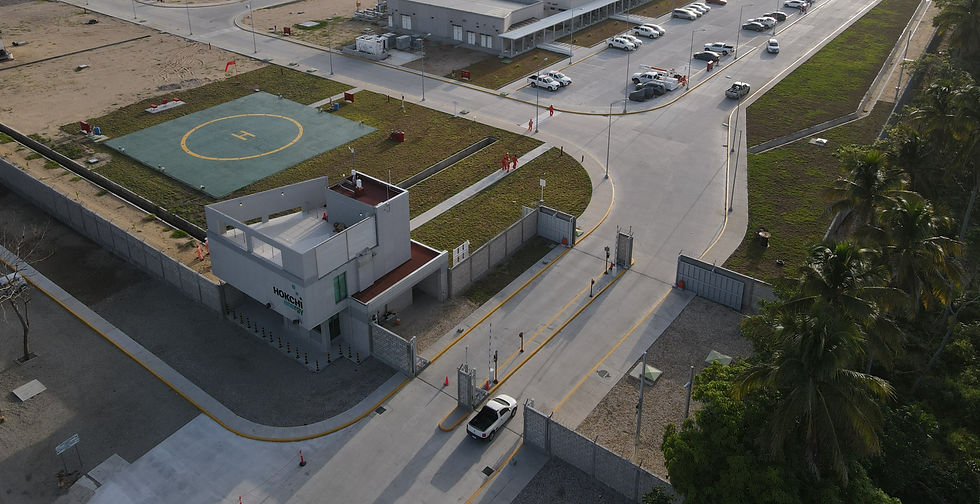
Layout criteria appear here that do not show up in API RP 752, yet shape the overall geometry of the site just as strongly: a minimum distance of around 15 meters between the property line and any occupied building (with the sole exception of the perimeter security building); a minimum of around 6 meters between parking areas and the perimeter fence to prevent vehicles being used as a foothold for scaling; an internal perimeter road for patrol with a cleared strip enabling CCTV visibility; sequential double-gate (airlock) access separating identity control from cargo control; functional segregation between the process zone and the administrative or logistics zone; security buildings with reinforced construction, autonomous electrical and communication systems and their own redundant HVAC.
None of this is exotic. But it rarely lands on the master plan table at the same time as facility siting, because each discipline arrives with its own set of drawings. The familiar result: when the layouts converge late, the adjustments are expensive.
The LATAM threat model matters before the fence
There is a more sensitive component that should be mentioned with care. Preliminary risk analyses on LATAM projects often include, alongside the classical risks — intrusion, theft of tools and materials, sabotage — three items that a consultant trained only in mature markets would need to learn to read: hydrocarbon theft directly from the pipeline (outside the plant property); access blockades or property takeovers by local actors — community or labor groups — used as a pressure tool against the operation; and variable response times from local security forces, which force the operator to sustain its own containment capability during the first hours of an incident.
These are not abstract risks. They drive concrete decisions: where to locate administrative offices and contractor areas, how to design the main access, how much electrical and communications autonomy the security building must have, how the contractor area is segregated from the rest of the plant, and where to place pipeline metering stations relative to the property line.
A master plan that ignores this layer ends up needing late mitigations — additional fencing, redesigned access, hardened buildings — that could have been resolved earlier through layout. In LATAM projects, reading this threat model with the same seriousness as fire and explosion is not optional. It is half of the problem.
Apparently minor changes, systemic impact
The other familiar pattern in this kind of project is the "architectural" change that, once in construction, stops being architectural. Relocating an access, changing the relationship between the control room and a meeting room, removing a planned use or adding new administrative areas tends to ripple into HVAC, pressurization, electrical distribution, internal circulations, evacuation routes and associated cost.
Seen on a plan, they look like minor adjustments. Seen from operations, they end up being engineering decisions taken late, when the technical and contractual room for negotiation is already narrow. That is the moment when the owner often pays twice: once for the development of what was missing, and again for the change orders that can no longer be negotiated from a position of strength.
In markets with more explicit contracting practice, the level of project definition at tender stage tends to be higher, and this kind of adjustment is debated before award. Where documentation discipline is looser, the same debate moves to the construction phase. It is the same technical decision, taken at the worst possible moment for the owner.
The takeaway
After working on this kind of project, I am convinced of one thing: technical architecture in Oil & Gas does not work on a blank sheet. It works on constraints — electrical hazardous area classification, process routing, maintenance access, evacuation, physical and asset security, noise, vibration, corrosion, climate, local codes, international standards, construction logistics and future operation. It is a discipline of integration, not of authorship.

In that logic, the master plan is not an early deliverable that gets replaced by more detailed drawings later. It is the framework that organizes the rest of the project. A well-developed master plan does not eliminate the risks of a plant. But it allows better decisions to be made before those risks get built in.
That, in the end, is what defines a complex project well done. Not how technically difficult it is. The capacity to make that difficulty invisible — so that, ten years into operation, no one has to remember why the building sits exactly where it does. It just works.
In critical infrastructure, architecture does not begin at the façade. It begins with understanding the process, the risk, and the people who will operate the facility for the next twenty-five years.
________________________________________________________________________
Fernando Pérez Kaparunakis is an architect specialized in complex architecture projects, with a focus on critical infrastructure, master planning and Facility Management for the energy industry. He has worked on onshore Oil & Gas, remote operational bases and large-scale facilities across Argentina, Mexico and the broader LATAM region. Founder of ARIA infrastructure.

Comentarios